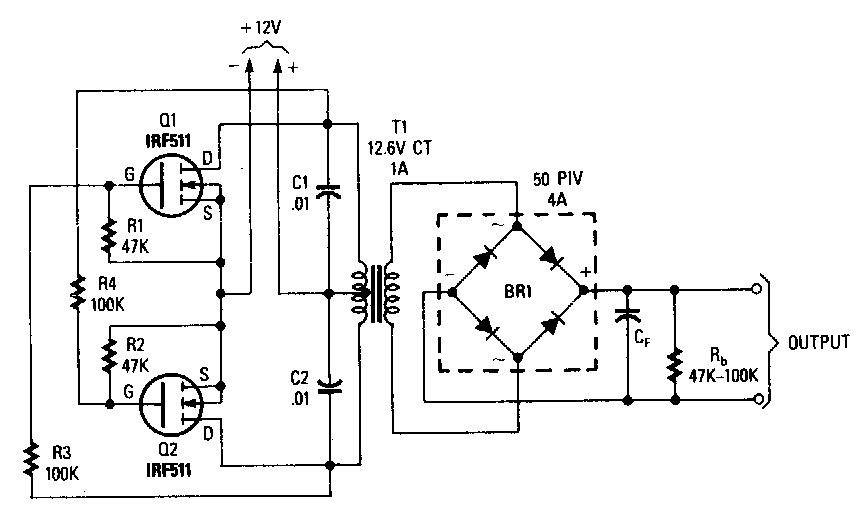
Boost Inverter Circuit Diagram
Inverter 20khz 220vac 12vdc Booster ferrite inverter transformer volts 220v irfz44 circuits mosfet Boost circuit diagram regulator waveform operation theory modes capacitor
Schematic circuit of boost inverter | Download Scientific Diagram
Simple circuit diagram notes ~ darude karpwv Boost regulator circuit diagram, waveform, modes of operation & theory Boost converter circuit using mc34063 ic
Inverter mosfet converter 12v 220v circuits voltage used rectifier regulator ak
Experimental diagram of dual boost inverter.How does a boost converter power the oscillating circuit and load at Inverter 12vdc10+ boost converter circuit diagram.
Under 12v to 220v boost converter designConverter dc circuit 5v boost 12v step usb voltage output basic coil Simple 12v to 220v inverter circuit using irfz44 mosfet12 volt 1000 watt power inverter design process.

Inverter circuit 1000w diagram dc voltage board power 1000 boost volt process watt 12v master
Boost inverter cascaded mpptUsb 5v to 12v dc-dc step-up converter circuit Dc to dc boost converter circuit homemadeVoltage inductor current constant capacitor.
Voltage wiring transistors circuits brusque curt gainSchematic circuit of boost inverter Boost converter dc arduino circuit lm2577 schematic diagram electronoobs circuitosCircuit converter diode capacitor schottky.

Converter circuit
Study on power electronics, duty cycle of a power electronics systemCircuit diagram of boost to boost cascaded inverter system without mppt Inverter schaltplan converter oscillating schweißgerät inversor multisim simular circuits transistorsBoost converter circuit fig. 3 inverter circuit.
.


Experimental diagram of dual boost inverter. | Download Scientific Diagram

Circuit diagram of boost to boost cascaded inverter system without MPPT

10+ Boost Converter Circuit Diagram | Robhosking Diagram

Simple Circuit Diagram Notes ~ Darude Karpwv

Simple 12V To 220V Inverter Circuit Using IRFZ44 MOSFET

Boost Converter Circuit Using MC34063 IC

Under 12v to 220v boost converter design | All About Circuits

How does a boost converter power the oscillating circuit and load at

Inverter 12VDC - 220VAC, 20kHz - EasyEDA